Take the boards out of the protective packages
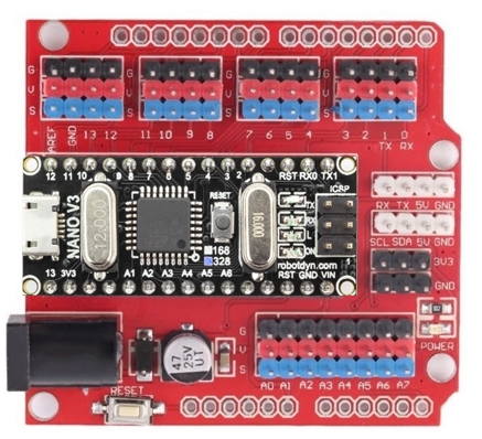
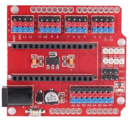
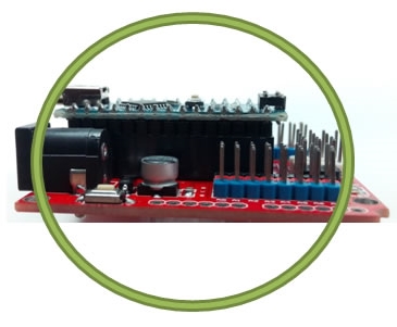
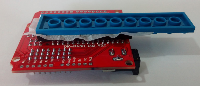
Line up the boards exactly the same as the pictures
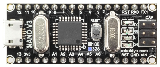
Press the small Nano board down into the large I/O Expander board
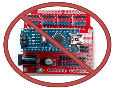
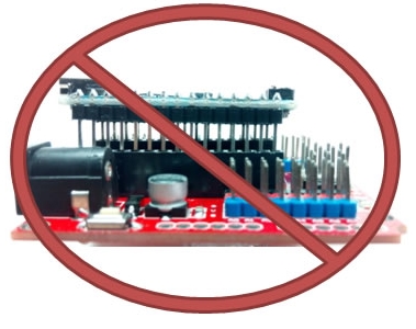
Make sure it isn't backwards!
Push it all the way down and in
Make sure it isn't sticking up
Plug the small end of the USB cable into the new BrainBlock
Plug the big end of the USB cable into your Laptop
Your BrainBlock is now ready to program with mBlock
Assembly - Part II
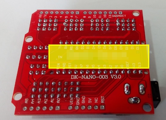
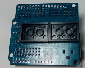
Actetone the bottom of the BrainBlock circuit board Just the yellow area
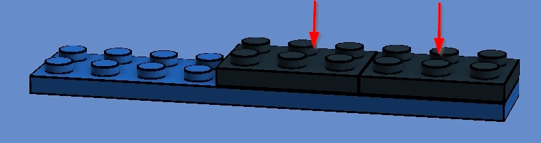
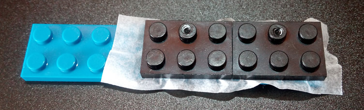
Build this simple jig
Use wax paper to protect the "blue" lego
Sand the tops of the "black" bricks
Acetone the tops of the "black" bricks
BEFORE you glue practise placing the bricks in the correct position Use the pins on the circuit board to help keep the blocks straight
The "black" bricks should not stick out past the edge of the board
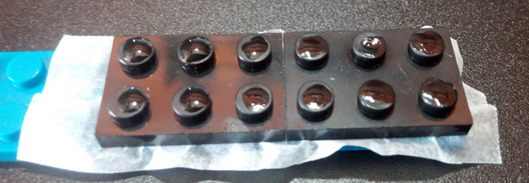
Put a small drop of SuperGlue on each of the 12 Lego bumps
Place together and hold firmly for 1 minute
Wait at least 5 minutes before removing the jig You don't need to hold it during this time
You're done! You're BrainBlock should look like this
Theory
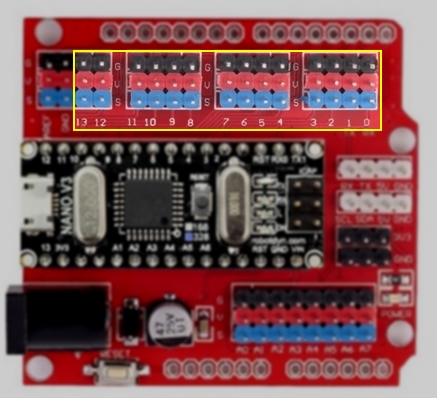
Digital Input and Output Pins
Digital means something is either On or Off (0 or 1) (High or Low) A button is a good example it is on or off (pressed or not)
An LED light can also
be digital (on or off)
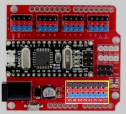
Analog Input Pins
Analog means something can be many different values or levels A volume knob on a stereo is a good example - it can be turn to any position between zero and Full-Volume
Black pins are G = Ground (-) Red pins are V = Voltage (+) Blue pins are S = Signal
Ground (-) and Voltage (+) provide 5 Volts of power.
This power comes from your laptop through the USB cable.
Ground is negative (-) power.
Voltage is positive (+) power. Signal pins are controlled by the brain, they can be turned on and off.
Now that your BrainBlock is ready you will can program and test it using mBlock. mBlock Setup Instructions


 Use wax paper to protect the "blue" lego
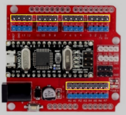 Black pins are G = Ground (-)
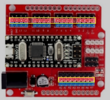 Red pins are V = Voltage (+)
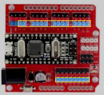 Blue pins are S = Signal