Xtreme STEM
DashX

RoboBloX

EyeBlock

EyeBlock

Theory

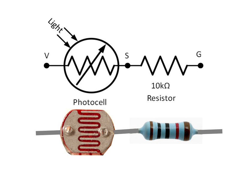
A photocell changes resistance as it is exposed to light. The more light it recieves, the less it resists the flow of electricity.
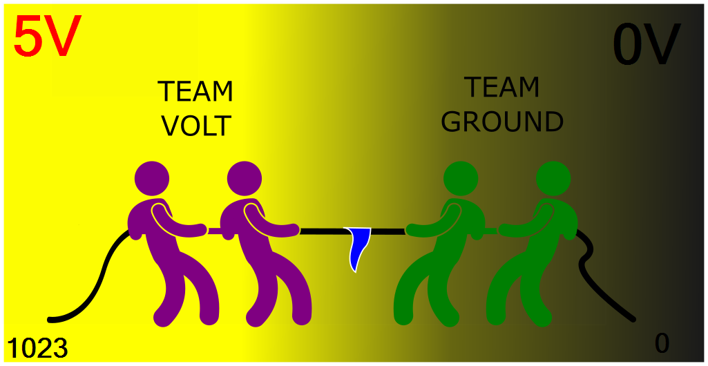
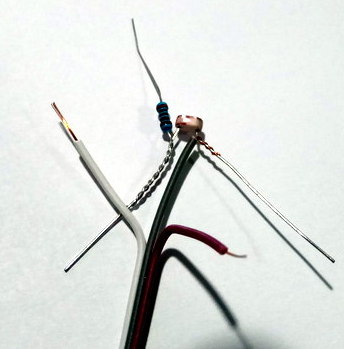
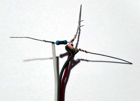
The circuit below is setup like a tug-of-war.
The 10k resistor always has the same strength, and is on team G for Ground (negative).
The photocell gets stronger as it gets more light, and is on team V for voltage (positive).
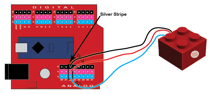
S (signal) is like the flag in the middle of the rope that shows who is winning.

Tuf of War


eb

Wiring


Assembly

  1. Cut Wire
    Cut the connectors off one end of the cable
  2. Wire
    Strip about 10mm off the end of each wire
  3. eye
    Twist one leg of the 10k Ohm resistor and Photoresistor together
    The twisted legs will be connected to the Signal wire later
  4. eye
    Twist the Voltage (middle) wire to the other (the unused) leg of the photoresistor
  5. eye
    Twist the Ground (left) wire to the other resistor leg
    Twist the Signal (right) wire to the joined legs (photoresistor and resistor)
  6. eye
    Solder and trim the the legs short
  7. Stop
    Check with Mr. Dash before continuing
  8. Drill Side of Block

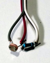
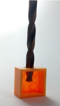
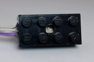
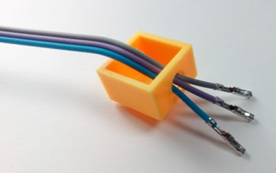
    Drill a 6mm hole in one side for the photocell
    Drill a 3mm hole in the opposite side for the wires


  9. Cable

    Use a pin to bend the latch that holds the black connector housing on
  10. Wire
    Pull the housing off each wire
  11. Wires in
  12. Wire
    Place the 3 pin housing on the ends of the wires
    Make sure the metal ends are the right way up so the plastic latch can click into place


Connection Diagram

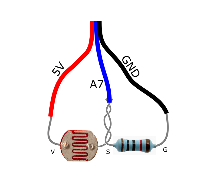
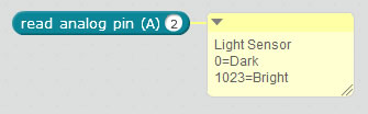
The EyeBlock can be connected to any Analog Input (A0-A7).
If the EyeBlock is connected backward no damage occures, but all readings are 0.

eb


mBlock

Hints

eb

Example Programs

eb


eb


Advanced

See the JoyBlock for an example of how to control the WiggleBlock using an Analog Input, you can use the same program with the EyeBlock.

Scroll to Top