Xtreme STEM
DashX

RoboBloX

LineBlock

LineBlock

Theory

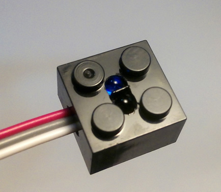
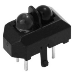
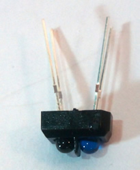
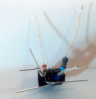
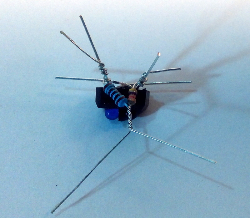
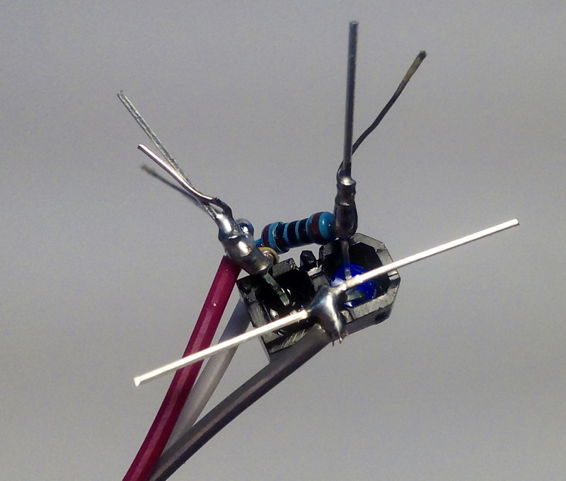
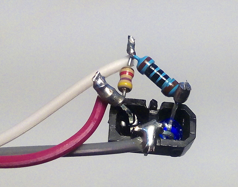
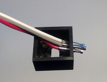
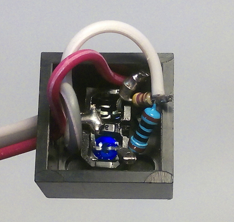
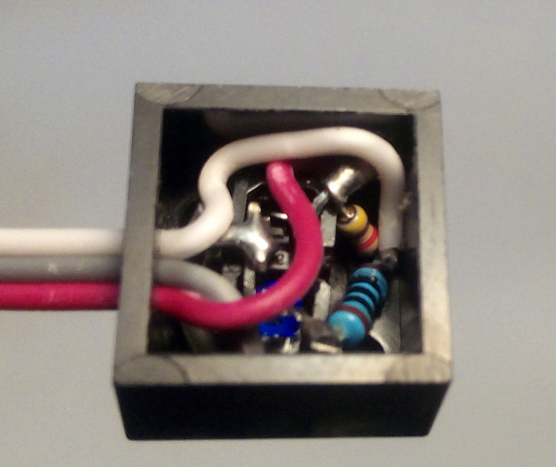
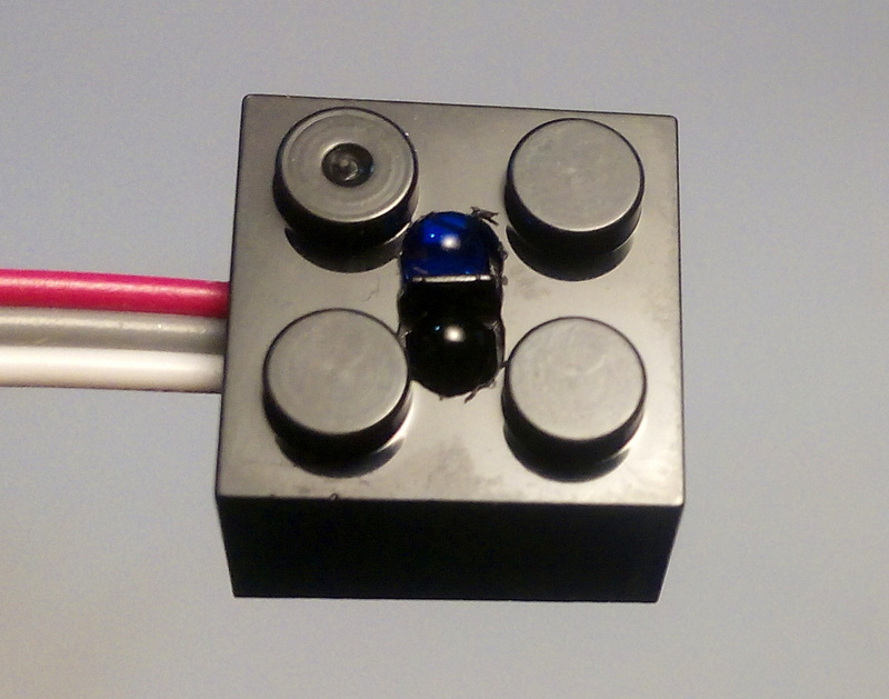
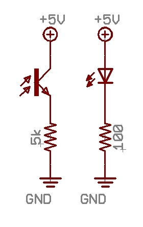
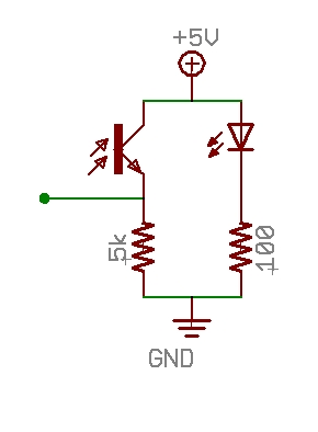
The LineBlock uses an Infrared LED and photodiode to detect how reflective a surface is. 

IR Sensor
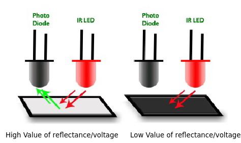
The LED emits infrared light, which then bounces off a surface, if the surface is reflective (like white paper) then lots of light is reflected back to the photodiode that detects how much IR light it is receiving.  When the sensor is placed near a dark or black object (or black line), then less light is reflected, and the photodiode reports a lower value.

The sensor can also be used as a distance sensor, since the further away an object is, the less light it reflects back to the sensor.

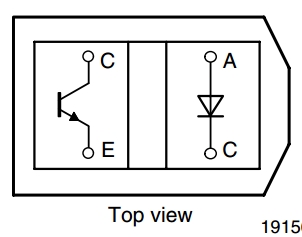
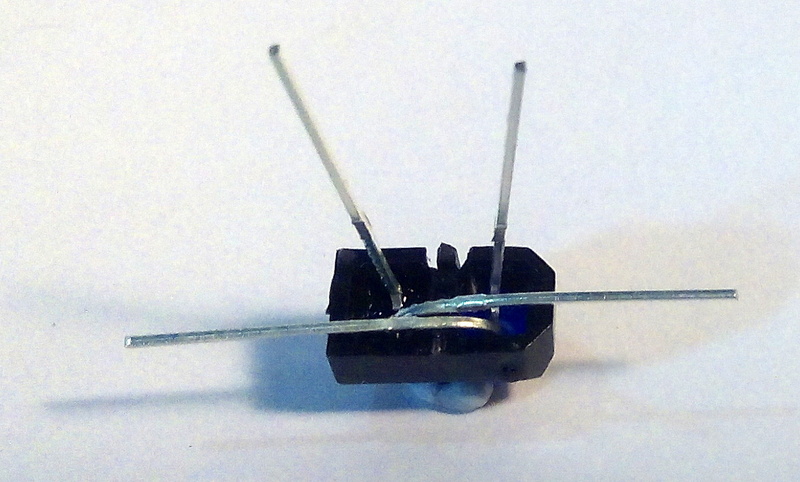
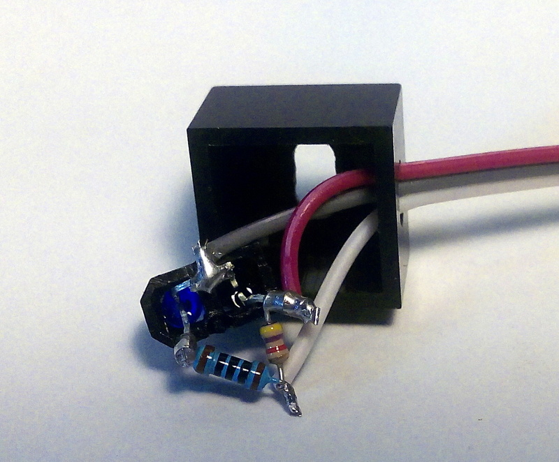
The part number of the sensor we will be using is TCRT5000, here is the datasheet for that part:
PDF


Sensor Sensor Pinout

Assembly

  1. Required Materials

    Materials
    IR Sensor
    Cable 3 Wire
    Connector 3 Pin
    Block 2x2
    Resistor 100 ohm
    Resistor 4.7k ohm


  2. IR
    It is very important not to mix up the
    Photodiode (black on the left)
    with the
    IR LED (blue on the right)
  3. LineBlock
    Cut or break off the 2 little black plastic legs in the middle
  4. Legs
    With the IR LED (blue) on the right
    Bend the two legs closest to you so they overlap
  5. IR
    Wrap the 100 ohm resistor
    Stripes = Brown Black Black Black Brown
    Around the IR LED's (the blue one) leg
  6. IR
    Wrap the 4.7k ohm resistor
    Stripes = Yellow Purple Red Gold
    Around the Photodiode's leg
  7. IR
    It should now look like this
  8. IR
    Twist the resistors together
  9. Cut Wire
    Cut the connectors off one end of the cable
  10. Wire
    Strip about 10mm off the end of each wire
  11. IR
    Hook the middle wire around the 2 legs that are bent together
  12. IR
    Wrap the left wire around where the resistors are twisted together
    (Take note that this wire will be your 'G' Ground wire)
  13. IR
    Wrap the right wire around the photodiode's leg
    (the one with the 4.7k resistor also attached)
  14. IR
    Solder all 3 wires and the resistors in place
  15. IR
    Cut off the extra leg length
    Be careful not to cut too close and cut the wire off
  16. Cable

    Use a pin to bend the latch that holds the black connector housing on
  17. Wire
    Pull the housing off each wire
  18. WireWire
    Place the cable into the block
  19. IR
    Pull the cable until the sensor is almost in the block
  20. Wire
    Place the 3 pin housing on the ends of the wires
    Make sure the metal ends are the right way up so the plastic latch can click into place
  21. Pen
    Place a silver strip on the side of the connector
    Make sure it is the wire that goes to where the two resistors are twisted together
  22. Stop
    Check with Mr. Dash before continuing
  23. IR
    Push the sensor down into the block until it fits in the slot
    You must be very careful that none of the 4 wires touch each other.
  24. IR
    Push the wires and resistors down into the block
    until another block can easily fit onto the bottom of the LineBlock.
    You must be very careful that none of the 4 wires touch each other.
  25. IR
    The sensor should just be poking out of the slot in the top
  26. Stop
    Check with Mr. Dash before continuing
  27. Glue
    Fill the block with hot glue
  28. GlueGlue
    Place wax paper on top of the LineBlock
    Then place a block on top and squeeze firmly together
  29. LineBlock
    You're Done!
    Your line block should look like this.


Connection Diagrams

  • SchematicSchematicSchematicSchematic
  • Analog Pins
    The LineBlock can be connected to any Analog Pin (A0 - A7)
    (Silver stripe always goes to G (GND))


mBlock

Hints

eb


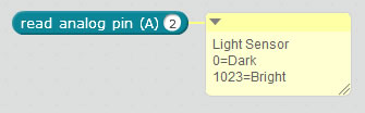
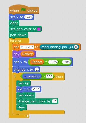
This sample program draws a live graph of the input from the analog sensor:

mblock

Scroll to Top